Consulting
Service
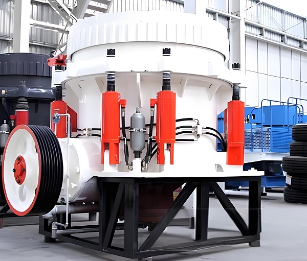
As a core piece of equipment in fine crushing operations in industries such as mining and infrastructure, the standardization of cone crusher installation and commissioning directly determines its operational stability, crushing efficiency, and service life. In actual operation, problems such as insufficient foundation precision, component assembly deviations, and improper parameter adjustments often lead to excessive equipment vibration, uneven output particle size, and frequent malfunctions. This article, based on the equipment's structural characteristics and on-site operational needs, outlines key technical points and precise parameter standards from pre-installation preparation, core processes, phased commissioning, to safety acceptance. It provides standardized operating guidelines for technicians, helping to avoid installation hazards, ensure the equipment quickly reaches its designed capacity and crushing precision, and lay a solid foundation for efficient production line operation.
Pre-installation Preparation: Laying a Solid Foundation for Stable Operation
The installation quality of the cone crusher directly determines its subsequent operating efficiency and service life. Sufficient preparation is required in the early stages in terms of site, equipment, and personnel to avoid potential hazards.
1. Site and Foundation Preparation The site must meet the space requirements for equipment operation and maintenance. A maintenance passage of ≥1.8 meters should be reserved around the crusher. The distance between the feed end and the feeder should be ≥1 meter, and the distance between the discharge end and the conveyor should be ≥0.6 meters. Foundation construction must strictly follow the installation drawings, using C35 or higher grade concrete. For small cone crushers (processing capacity ≤100t/h), the foundation thickness should be ≥800mm; for large models (processing capacity ≥500t/h), it should be ≥1200mm. Embedded anchor bolts (material Q355B) must be fixed using positioning templates. Bolt spacing error ≤±2mm, verticality error ≤1mm/m. Concrete curing time ≥10 days, and installation can only proceed when the strength reaches ≥90% of the design value. The horizontal error of the foundation top surface should be ≤0.5mm/m, and the surface should be free of defects such as honeycomb and cracks. Meanwhile, the site must be equipped with a stable power supply (voltage fluctuation ≤ ±3%) and a water supply system (cooling water pressure 0.3-0.5MPa). For environments with high dust levels, the installation location of dust removal equipment must be planned in advance.
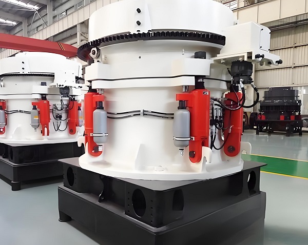
2. Equipment Inspection and Parts Verification: After unpacking, check each component against the equipment list, focusing on core components: The moving and fixed cones should be free from transport deformation, cracks, and dents; the frame welds should be full, without any detachment or porosity; rotating parts such as the eccentric shaft and drive shaft should be free from bending, and bearing lubrication channels should be unobstructed. Verify the model and quantity of vulnerable parts (linings, seals), and ensure that anchor bolts, gaskets, lubricating oil, and other accessories are complete. Pre-test auxiliary equipment such as motors and reducers; the motor insulation resistance should be ≥ 2MΩ, and the reducer gears should have no meshing deviation. Pay special attention to checking hydraulic system components (cylinders, valves, oil pipes) to ensure there are no leaks or corrosion, and that the seals are intact.
3. Personnel and Tool Preparation
Installation personnel must possess mining machinery installation qualifications, be familiar with the structural principles of cone crushers, and undergo prior technical briefings. Essential tools include: a frame level with an accuracy of 0.02mm/m, a torque wrench (range 50-300N・m), lifting equipment (rated load ≥ 1.5 times the equipment weight), feeler gauges, dial indicators, etc. Electrical installation must be performed by a professional electrician. Safety helmets, non-slip shoes, and insulated gloves must be provided. Warning signs should be set up on site, and restricted areas should be designated.
Core Installation Process: Precise Control of Key Aspects
Installation follows the principle of "main body first, then accessories; fixing first, then connection; rough adjustment first, then fine adjustment," focusing on controlling the assembly accuracy of the frame, transmission system, crushing chamber, and hydraulic and lubrication systems.
1. Frame Installation and Leveling
Use lifting equipment to smoothly hoist the frame onto the foundation, ensuring precise alignment of the base bolt holes with the anchor bolts. Initially tighten the nuts (not yet to the rated torque). Measure the longitudinal and transverse levelness of the frame using a frame level. Correct the levelness by adjusting the stainless steel shims (0.2-5mm thick) under the base, ensuring the levelness error is ≤0.2mm/m. After correction, tighten the anchor bolts in a diagonal sequence, using the torque value specified in the equipment manual (usually 120-250N・m). After tightening, recheck the levelness to prevent frame displacement during tightening. After frame installation, check the contact surface between the frame and the foundation; the gap should be ≤0.1mm to ensure even stress distribution.
2. Transmission System Installation and Calibration The installation of the transmission system directly affects power transmission efficiency, requiring strict control of coaxiality and meshing accuracy. First, install the motor and reducer. Secure the motor base firmly, ensuring the parallelism error between the motor shaft and the reducer input shaft is ≤0.15mm/m, and the center distance deviation between the two shafts is ≤±0.3mm. When using a coupling, the coaxiality error of the coupling should be ≤0.05mm, the end face gap should be 2-4mm, and the elastic pad should be installed correctly without misalignment. When using a belt drive, the pulley alignment deviation should be ≤0.5mm, and the belt tension should be such that the midpoint sinks 8-12mm when pressed. When installing the eccentric shaft and drive shaft, ensure the bearings are properly assembled, the bearing clearance is controlled at 0.03-0.08mm, and add lithium-based grease to half the bearing cavity volume. Rotation should be smooth and without jamming.
3. Crushing Chamber Assembly and Gap Adjustment: Before installing the moving and fixed cones, clean the surface oil and impurities. Check that the liners (crushing wall, grinding bowl wall) are undamaged and deformed, and that the liners fit tightly to the cone with a gap ≤0.5mm. The liners are fixed using a bolt + locking block structure. The bolt tightening torque should be as required in the instruction manual (usually 80-150 N·m), and anti-loosening washers should be installed to prevent loosening. After installation, adjust the gap between the moving cone and the fixed cone (initial gap at the discharge port). For small models, adjust to 5-10mm; for large models, adjust to 10-15mm. This can be achieved using a hydraulic jack or adjusting nut. Measure the gap at four evenly distributed points around the discharge port using a feeler gauge; the difference should be ≤1mm to ensure uniform force distribution within the crushing chamber.
4. Hydraulic and Lubrication System Installation: Before connecting the hydraulic system pipelines, flush the pipelines with high-pressure oil to remove impurities. Install sealing rings (using oil-resistant rubber) at the pipeline interfaces. Tighten bolts evenly and ensure no leakage. Fill the hydraulic oil tank with No. 46 anti-wear hydraulic oil to the center line of the oil window. Start the hydraulic pump and run it unloaded for 5-10 minutes to purge air from the system. Check that the cylinder extends and retracts freely and that the pressure is stable within the design range (usually 10-16MPa). The lubrication system uses a centralized oil supply method. The oil tank is filled with No. 32 or No. 46 gear oil, and the oil level meets the requirements. Check that the oil pump, filter, and cooler connections are unobstructed. After startup, ensure sufficient oil supply to all lubrication points (bearings, gears), normal oil return, and oil temperature controlled between 30-55℃.
5. Electrical System Installation Electrical installation strictly follows the "Construction and Acceptance Specifications for Electrical Installation Engineering." The wiring of motors, sensors (temperature, pressure, vibration sensors), and control cabinets is secure, and the grounding resistance of the grounding wire is ≤4Ω. The control cabinet is installed in a dry, ventilated, and easily accessible location, with a distance of ≥1.5 meters from the equipment. Wiring is neat and clearly labeled. Install emergency stop buttons, indicator lights, frequency converters, and other components, and test their functions to ensure they are normal. The motor rotation direction should match the arrow on the equipment label, and the frequency converter speed range should meet design requirements (usually 5-50Hz).
Phased Commissioning: Achieving Efficient and Stable Operation
Commissioning is conducted in the order of "no-load commissioning - load commissioning - parameter optimization," gradually troubleshooting problems to ensure the equipment reaches its designed processing capacity and crushing accuracy.
1. No-load commissioning: Verifying equipment operational stability. Before no-load commissioning, recheck the tightness of all bolts, remove debris from the crushing chamber, and confirm that the lubrication, hydraulic, and electrical systems are functioning correctly. Start the equipment as follows: First, start the lubrication system and run it for 5 minutes to ensure normal oil supply; then start the hydraulic system and adjust the discharge port to the set value; finally, start the main motor, jogging it 2-3 times to observe that the motor rotation is correct and there are no abnormal noises or severe vibrations. After jogging normally, run the equipment continuously under no-load for 4-6 hours, monitoring key parameters: motor current should be 20%-40% of the rated current, bearing temperature ≤70℃, vibration speed ≤3.5mm/s, and the hydraulic system pressure should be stable with no leakage or abnormal noises. If excessive vibration occurs, check the frame fixation, coupling coaxiality, or dynamic cone balance; if the bearing temperature is too high, check whether the lubrication is sufficient or the cooling system is functioning properly.
2. Load commissioning: Optimizing crushing effect. After the no-load commissioning is successful, conduct load commissioning, gradually increasing the feed rate to avoid full-load operation at once. Initially, feed at 30% of the designed capacity and run for 1-2 hours, observing the material crushing state: the material should be evenly distributed within the crushing chamber, without uneven loading or blockage, and the discharge particle size should meet preliminary requirements. Adjust the discharge port size via the hydraulic system and optimize the gap based on screening results to ensure that the proportion of qualified particle size material is ≥85%. Gradually increase the feed rate to 50%, 80%, and 100%, running stably for 2 hours after each increase, recording parameters such as throughput, discharge particle size, motor current, and energy consumption. Test the crushing ratio (usually 4-8) and product particle shape; the needle-like and flaky content should be ≤10%. If the particle shape is unsatisfactory, adjust the moving cone speed or the crushing chamber design; if the throughput is insufficient, check the feed uniformity or the discharge port size.
3. Common Problems and Solutions
Problems and solutions that may occur during load commissioning:
① Unstable discharge port gap: Check for hydraulic system pressure leaks and adjust the overflow valve pressure to the design value;
② Motor overload: Excessive feed rate or excessive material hardness; reduce feed rate or replace with a suitable cavity type;
③ Uneven discharge particle size: Excessive deviation in the gap between the moving cone and the fixed cone; readjust the gap and tighten;
④ Abnormal equipment noise: Loose liner or component interference; stop the machine, tighten the liner bolts, and check for interference;
⑤ Hydraulic system overheating: Cooler blockage or insufficient oil; clean the cooler and replenish hydraulic oil.
Safety Specifications and Acceptance Standards
After installation and commissioning, a comprehensive acceptance test must be conducted, and a maintenance system must be established to ensure long-term safe operation of the equipment.
1. Safe Operating Procedures
Operators must be trained and qualified before starting work and must strictly adhere to the operating procedures: Start-up sequence: Lubrication system → Hydraulic system → Main motor → Feeder; Shutdown sequence: Feeder → Main motor → Hydraulic system → Lubrication system (delay shutdown of the lubrication system by 5 minutes to ensure adequate lubrication of components).
Do not open the observation door or perform maintenance while the equipment is running. Do not put hands or foreign objects into the crushing chamber. In case of emergency, immediately press the emergency stop button and disconnect the power supply before proceeding. Regularly check that the safety protection devices (protective covers, guardrails) are intact; it is strictly forbidden to operate the equipment without these devices.
2. Installation and Acceptance Standards
Acceptance must meet the following indicators:
① Equipment levelness error ≤ 0.2mm/m, frame and foundation tightly fitted;
② Transmission system runs smoothly without tooth slippage or grinding, coupling coaxiality ≤ 0.05mm;
③ Hydraulic system pressure stable, no leakage, discharge port adjustment flexible, clearance deviation ≤ 1mm;
④ Under no-load operation, motor current, bearing temperature, vibration speed, and other parameters meet requirements, continuous operation for 4 hours without failure;
⑤ Under load operation, processing capacity reaches over 95% of the design value, discharge particle size qualification rate ≥ 85%, needle-like and flaky content ≤ 10%, unit energy consumption meets the equipment manual requirements. After acceptance, compile and file the installation drawings, commissioning records, test reports, and other relevant documents.
3. Pre-Maintenance Requirements: Hand over the equipment manual and maintenance manual to operators, and train them on key points of daily inspection: daily checks of bolt tightness, lubrication and hydraulic oil levels, and abnormal noises during equipment operation; weekly checks of liner wear, belt tension, and filter cleanliness; monthly changes of lubricating oil (replace after the first 500 hours of operation, and every 2000 hours thereafter), and cleaning of the oil tank and filter; quarterly comprehensive inspection of the hydraulic system, and replacement of aged seals. Establish a maintenance log to record operating parameters, troubleshooting, and replacement cycles of vulnerable parts, ensuring long-term stable operation of the equipment.
The installation and commissioning of a cone crusher is a systematic project that requires adherence to the principles of "precise assembly, scientific commissioning, and strict acceptance." By standardizing site preparation, strictly controlling the levelness of the frame and the coaxiality of the transmission system, and precisely adjusting the crushing chamber clearance, a solid foundation for equipment operation is ensured. Step-by-step commissioning under "no-load - load" conditions, optimizing hydraulic, lubrication, and electrical system parameters, can effectively improve crushing efficiency and product quality. Following safe operating procedures and post-maintenance requirements can significantly reduce the risk of failure and extend the equipment's service life. The full-process specifications and technical points described in this article can help enterprises reduce installation and maintenance costs, fully leverage the technical advantages of cone crushers, and provide reliable equipment support for large-scale production.


Company: Zhengzhou ZhongCheng environmental protection equipment co., LTD

Company address: 36 xueyuan road, Zhengzhou City, Henan Province, China.

Whatsapp:+86-18738194110


Our Email

Our phone
 86-18738194110
 86-18738194110

Save Time! Get A Detailed Quotation Quickly.


 2024-11-01